
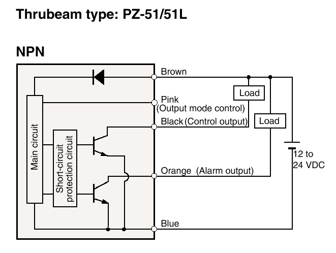
The PZ-51L has an open NPN collector output (actually two, the other is for "alarm" purposes). Depending on how the "output mode control" (pink wire) of RX is connected--tied to ground or Vdd--the sensor could be made to switch the open collector NPN on when RX senses the IR beam (no object detected) or when it fails to (object is blocking the beam). In all the circuits below the PZ-51L is used in the "light-on" mode, meaning the NPN is switched on when RX detects the IR beam.
Here are some pertinent specs, schematics, and diagrams lifted off a Keyence pdf catalog (came in a CD-ROM).


I initially intended to use the sensor in a throughbeam configuration, but to simplify installation and do away with alignment problems I decided to use it retroreflectively--i.e., TX and RX are side by side facing the same direction with RX sensing the reflection of the TX IR beam. Because the intensity of the light is much weaker in retroreflective mode the detection distance is much shorter than in throughbeam mode.
The PZ-51L TX and RX were placed side by side and glued together using double-sided foam tape. The pair was then just stuck using foam tape again to the jamb in the hallway about a meter off the floor. Anyone crossing would intercept the IR beam and reflect part of it back towards RX thus triggering it. There's a "SENS" trimmer on top of RX used to control its sensitivity. This had to be set to maximum to have RX detect people crossing. Even at maximum, however, sense distance was less than a meter. Type of clothing material may have an effect on how well the person is detected.
The initial circuit I developed back in 2001 was based on an LM311 comparator. I'm not going to put up the schematic since it's close to being a most incompetent design and so don't want anyone using it. It didn't even have a voltage regulator IC. Suffice to say it used RC timing (to provide seconds of time delay and keep the lights on) and a voltage reference to let the comparator know when to switch its output. Comparator output was connected directly to a 12-volt relay--I wouldn't design something like that now, but back then I just copied from an electronics textbook which showed just that. I didn't have a flyback diode across the relay coil--yet another faulty design. The relay then switched the lights on and off. Even with all the bad design elements, however, the circuit worked. I'd probably freak out now if I hooked up an oscilloscope to it.
The next year I scrapped the circuit--leaving the PZ-51L as is--and installed something decent. It was based on the 555 timer in a monostable mode. A pull-up resistor was connected to RX's "control" NPN collector (black wire). And that collector output was tied to the 555's pin2. So whenever the NPN was switched on (object detected) output of the 555 went high for a duration determined by RC. Instead of a relay, a MOC3021 optoisolator was used to trigger a Teccor Q4004L4 triac which then switched the lights.
The following year (2003) I completely changed the circuit again, using a CD4023 triple 3-input NAND with two of them wired up a simple RS flip flop, a 555 in astable configuration to provide a 16Hz output, and a CD4040 ripple counter which was clocked by the 555. I then NANDed three counter outputs to obtain a desired time duration. I also included a sonalert buzzer which was switched on (via an NPN) by one of the counter outputs. This buzzer sounded only during the last few seconds of the countdown thus alerting the user that darkness was about to descend upon him. In 2004 I made further (and final) revisions ending up with the following circuit which I will describe in detail.

CNT pin14 count = 512
CNT pin2 count = 32
CNT pin3 count = 16
RA = 30Kohms
RB = 30K
CT = 1uF tantalum
CF = 1uF aluminum electrolytic
PS = "wallwart" DC power supply, unregulated, no load output: 16VDC
VR = LM7812 +12V 1000mA voltage regulator
P-T = Keyence PZ-51L transmitter
P-R = Keyence PZ-51L receiver
TIM = NE556 dual timer
CNT = CD4040 ripple counter
NAND = CD4023 triple 3-input NAND gate
QB = S9013 NPN transistor ICmax = 500mA, hFE-min = 60
QR = S9015 PNP transistor ICmax = 100mA, hFE-min = 100
D1, D2 = 1N4148 signal diode
BUZ = sonalert buzzer
OPTO = MOC3021 optoisolator with triac driver output
TRIAC = Teccor Q4004L4 triac 400V 4A
LSW = wall switch of light
L = lamps, used to be incandescent, now CFL.
all resistors are 1/4W 5% tolerance
Here's how the circuit operates. When an object reflects the infrared beam and RX detects it ights will be immediately turned on. Simultaneously the buzzer will sound for around 2 milliseconds to give an audible feedback that the system has been activated. After around 32 seconds the buzzer will sound again, softly--due to the 30K resistor in series with BUZ and D1--for about 3 seconds, after which both lights and buzzer will be turned off. If a person crosses the IR beam while the lights are already on, then the counter will be reset and will begin counting half a minute of time again as soon as the person is no longer within the detection zone. If a person remains stationary and reflects the IR beam continuously the counter will remain reset and the lights will remain on indefinitely.
TIM.a is wired in astable mode and provides a continuous 16Hz square wave for CNT clock input. Period of 555 is given by:
T = 0.693(RA + 2RB)CT
where:
T = period, in seconds
RA = resistance, in megohms
RB = resistance, in megohms
CT = capacitance, in mircofarads
Using a 1uF tantalum capacitor and resistors RA = RB = 30Kohms gives a period of 0.06237 sec, a very good approximation of 1/16 sec. By counting multiples of 16 we can thus make the counter time in seconds. (Note: These are theoretical figures. Back then I didn't have a scope nor a any meter that could measure frequency or even capacitance to determine the actual output frequency of the 555.)
NAND.s and NAND.r form a simple RS latch. Inputs to this latch must normally be high. When input goes low that particular gate's output will go high. CF is a filter capacitor to prevent line noise from falsely triggering the latch.
When P-R is activated, its internal NPN transistor is turned on. NAND.s input is therefore brought low. If NAND.s is outputting a low it will be triggered to output a high. If NAND.s output is already high there is no change and no harm done. When NAND.s output is high lights are turned on.
Buzzer will begin sounding when CNT count reaches 512. NAND.rst output will go low when CNT reaches 560 (or around 35 seconds), triggering NAND.r to output high which then resets CNT and switches off BUZ. Simultaneously, NAND.s output will go low, turning off the lights.
The CNT outputs which are connected to NAND.rst inputs are 210=512, 26=32, and 25=16, or a total of 560 counts. Because the clock is running at 16Hz, 560 counts translates into 560 / 16 = 35 sec. When count reaches 512, pin 14 of CNT goes high. This turns on BUZ. Because CNT has limited drive capability and since volume of BUZ doesn't need to be high for this alert a 30K resistor is placed in series. Three seconds later, when count reaches 560, NAND.rst output goes low. Pins 12 and 13 of NAND.r are pulled low which causes output of NAND.r to go high and output of NAND.s goes low. CNT is reset and remains reset. NAND.rst output then goes high again. The circuit then is at its beginning state once more.
Because of the particular outputs of CNT used, the buzzer will be on for the last 3 seconds of the count. This will provide an audible signal when the lights (load) are about to go out. If the buzzer needs to be on for a second or two longer then CNT output 27=64 can be used instead. D1 and D2 allow BUZ to be used independently by CNT and TIM.b.
Whenever P-R is activated--even if L is already on--CNT is reset to zero, thus extending the time L is on by another cycle (~35sec). This retriggerability is achieved by a transistor inverter (QR) and a voltage divider (Rr1 and Rr2). When voltage across Rr1 is high CNT reset pin11 will be high (>50% system voltage) thus causing CNT to reset. The values of Rr1 and Rr2 were chosen so that current sinking/sourcing by NAND.r is minimal and so that proper voltages will be present to reset CNT. When P-R is activated QR is turned on. Voltage across Rr1 goes from low to high. This then causes CNT to be reset. If a person stands in front of P-R, CNT will be continuously in reset mode, thus preventing any count. L will therefore be on indefinitely. Here's a table to make all this more comprehensible.

When P-R is activated CP begins charging. At this instant TIM.b pin8 goes low which then starts TIM.b. CP charges very rapidly and after it has charged voltage across it stays high until P-R is activated again. TIM.b output goes high for just a couple of milliseconds (given RT2 = 220K and CT2 = 0.01uF, theoretical pulse width is 1.1RC = 2.4ms), producing a brief clicking sound. The sound serves as a nonobstrusive indication that P-R has been activated (or reactivated if lights are already on). To make certain that sound does not last longer than this very brief period, triggering of TIM.b makes use of capacitor coupling. Given CP = 0.001uF and RP = 390K the negative trigger pulse is around 0.4ms--much shorter (as it should be) than the monostable output pulse. No negative pulse will occur again unless P-R output goes high then low again. Thus, even if a person were to stand in front of P-T/ P-R indefinitely, BUZ will still sound for only 2ms. He has to move away and then back again to re-trigger TIM.b.
The load is switched by a power triac which in turn is triggered by a triac output optoisolator. No snubbing circuit is necessary. OPTO needs 15mA to ensure proper turn-on of its LED. QB has a minimum current gain of 60 and a VBE of 0.7V. Maximum base resistor should therfore be around 45K. A 20K resistor was chosen to ensure more than enough collector current will be available. The actual current delivered to the LED of OPTO is determined by the current limiting resistor in series with the load. In this case the 470 ohm provides about 21mA.
Except for the AC adapter that's plugged into the outlet and the PZ-51L, the entire circuit is in a small box that's just glued to the concrete wall. The thing is, just a few days ago I needed to add a circuit--for a totally different application--in that box, one that will be using the same power supply. Trouble was there wasn't enough space. So even as I didn't wish to retire the above circuit I was forced to.
Given what the above circuit does--how simple the requirements are--a single "primitive" microcontroller suffices to replace all the ICs and practically all the discretes, thus freeing up more than enough space. Thus the latest version of the photoelectric sensor circuit was born.

MCU is a Microchip PIC10F202. Internal weak pull-up is enabled so P-R NPN collector can be tied to the MCU's pin (configured in firmware as input of course) without an external pull-up resistor. The transistor at output GP2 is a 2N7000 MOSFET.
Operation is similar to the preceding circuit. In fact I tried to mimic everything about it. When sensor first detects an object a click is sounded, the load is turned on, and countdown begins. The "click" is simply to alert user that a (re)detection has occurred and that countdown has been started/reset. If object remains within the detection zone no further clicks are sounded and countdown will not commence until object has left the zone. Once countdown has commenced and before it has ended and an object again crosses the zone, countdown is canceled and reset and a click is sounded. Three seconds before countdown ends a series of clicks are sounded until countdown ends. The three-second series of clicks warns the user of the pending lights switch-off. When countdown ends, buzzer and lights are switched off.
The only noticeable difference to the user between this and the previous circuit is the replacement of the continuous buzzer sound with a series of clicks during the last three seconds of countdown. The change is due to the fact that I needed to attenuate the buzzer volume. Placing a 10K resistor in series with BUZ lowered the volume of the last-three-second alert alright. But it also made the clicks (when object is first detected) barely audible. I toyed around with toggling BUZ every timer0 tick--on for one tick and off during the next, effectively doing a pulse width modulation at 50Hz with a 50% duty cycle. Didn't sound good. Kind of grating actually. So after a little experimentation I decided on a series of 10ms clicks spaced 200ms apart (5% duty cycle). This by the way is the same audible alert pattern I used in a motion detection circuit.
I won't go into the details of the firmware since it's short and relatively simple. There should be enough comments therein to make the whole thing easy to comprehend.
/* Photoelectric timed switch June 19-20 2011 Edwardson Tan processor = PIC10F202 compiler = Hi-Tech C Lite v9.80 */ #include__CONFIG (WDTEN & UNPROTECT & MCLRDIS); // config if using Hi-Tech C v9.80 // ======================================================================================================== // values for the following defines can be modified by user to suit the application #define loadonms 30000 // how long lights will be on, in milliseconds. this is the countdown period #define alertms 3000 // how long last-few-seconds alert will sound right before load is switched off, in milliseconds #define clickintervalms 200 // duration between clicks for last-few-seconds alert, in milliseconds // ======================================================================================================== #define t0end 39 // end value of timer0 to signal "overflow". used in conditional statement "if (TMR0 == t0end)" #define t0tick 10 // rounded-off timer0 tick in milliseconds = t0end * prescale * 1e-6sec * 1000 = (39)(256)/(1000) = 9.984ms #define timetilloadoff loadonms/t0tick // number of t0ticks before lights are switched off. this is the countdown period #define timetilbeep timetilloadoff - alertms/t0tick // number of t0ticks before 3-second beep starts sounding to alert user that lights are about to be turned off #define clickinterval clickintervalms/t0tick // duration of last-few-seconds alert in terms of number of t0ticks #define sw GP0 // open collector output of Keyence PZ-51L IR receiver NPN #define buz GP1 // sonalert buzzer 1" diameter #define load GP2 // 2N7000 switches MOC3021 which switches Q4004L4 triac which switches load #define int1 bit #define int8 unsigned char #define int16 unsigned int #define on 1 #define off 0 #define yes 1 #define no 0 // ======================================================================================================== int1 reset; // when writing to this flag: 1 = during current t0 tick sw is high (no object in detection zone); 0 = during current t0tick sw is low (object in detection zone) // when reading this flag: 1 = during the last t0 tick, sw was high (no object detected); 0 = during the last t0 tick sw was low (object was in detection zone) int1 countdown; // 1 = countdown to load switch-off is underway; 0 = countdown not ongoing int8 COUNT; // records how many t0 ticks from the last beep. used only during last-few-seconds alert. this variable cleared whenever sw is low int16 ELAPSEDTIME; // records how many t0 ticks have elapsed // ======================================================================================================== void main() { TRIS = 0x1; GPIO = off; OPTION = 0b10000111; // wake up on change off, weak pull ups on, timer0 prescaler = 1:256 TMR0 = 0; reset = off; countdown = off; while(1) { if (TMR0 >= t0end) { TMR0 = 0; CLRWDT(); // according to datasheet WDT nomimal timeout is 18ms buz = off; // buzzer is turned off every timer0 tick. Thus all beeps last only a maximum of one timer0 tick. Each beep will sound more like a click than a beep if (sw == hi) // sw is high when no presence is detected { reset = yes; if (countdown) { ++ELAPSEDTIME; if (ELAPSEDTIME >= timetilbeep) { if (++COUNT >= clickinterval) { buz = on; // last-few-seconds alert before light is turned off. consists of 10ms beeps every clickinterval COUNT = 0; } } if (ELAPSEDTIME >= timetilloadoff) // countdown ended so turned off buzzer, load, and clear countdown flag { buz = off; load = off; countdown = off; } } // if (countdown) } // if (sw == hi) else // sw is low when object is in detection zone { if (reset) // if NPN collector was high during the previous checks then turn on buzzer now since object has been detected. buzzer will be turned off during the next timer0 tick. Therefore this beep will last only for a max of 10ms, thus sounding more like a click than a beep. if NPN collector had been low then it means object has not moved out of the field of detection, so do not issue a click buz = on; load = on; reset = off; countdown = on; ELAPSEDTIME = 0; COUNT = 0; } // if sw == lo } // if (TMR0 >= t0end) } // while(1) } // void main()
No comments:
Post a Comment